Pressure sensors belong to the group of pressure measuring devices and offer precise and reliable solutions for almost every task in the field of pressure measurement. These solutions can be of various types, which is why there are many different pressure sensors, which can often be further configured (e.g. measuring range or process connection). However, the operating principle of all these different pressure sensors is the same: the physical quantity pressure is converted into a standard industrial signal.
Pressure sensors are often also called pressure switches, pressure transmitters or pressure transducers.
High quality pressure sensors by MP-SENSOR
MP-Sensor offers you a wide range of electronic pressure sensors. More precisely, the product portfolio currently includes 11 different sensor types, each of which can be individually configured. All pressure sensors from MP-SENSOR are characterized by their extremely compact design. Among other things, however, the designs differ in terms of housing material, housing shape, number and type of outputs and operability. Furthermore, the measuring range as well as the connections (both electrical connections and fluid connections) are freely selectable for most designs. Due to all these intelligent and versatile configuration possibilities, MP-SENSOR can offer most customers pressure sensors individually adapted to their respective requirements. If your requirements are not yet covered by the existing portfolio, please do not hesitate to contact us directly.
- Extremely compact designs
- Numerous configuration options
- Wide range of applications
- Robust and durable
Areas of application
Our pressure sensors are suitable for a wide range of applications, especially in the pneumatic sector, in hydraulic circuits and in the process industry. Thanks to various measuring ranges between -1 and 600 bar, a very wide spectrum is served here. Examples for pneumatic applications are vacuum lifting technology or tool changers. The pressure in a hydraulic system is typically measured on injection molding machines, elevators or working machines. In process technology, the pressure of a gaseous or liquid system fluid or the medium to be processed is often monitored.
For vacuum lifting technology, the PICO-02 is particularly suitable. Thanks to its digital display, the use of the PICO-02 means that no external control is required. Instead, the sensor can take over the control of actuators or relays by programming it accordingly via the display and keys.
If the vacuum lifting technology is implemented in a robotics application, the pressure sensor of choice would be the "Inline" type. This miniature sensor is not only compact and lightweight, but can also be installed in the simplest way. All that is required is to cut open the pneumatic hose at the desired point and insert it into the "Inline".
In the field of tool changers, for example, the F08 is ideally suited, as it can be easily configured to meet the customer's specific requirements. In addition, the sensor can be delivered preset with regard to adjustable parameters according to customer requirements.
With our latest pressure sensor P.Touch, we are completing the generation change of high-end designs in the pressure sensor sector. This means that a modern user interface by means of touch screens and an understandable and intuitive operation has also been implemented in the process sensor market. Due to a high measuring range between 0 and 600 bar, the P.Touch with a ceramic measuring cell is particularly suitable beyond the pneumatic areas for applications in the process industry and for hydraulic applications.
Types of pressure
Atmospheric pressure
The atmospheric pressure is the most important pressure for us humans. It describes the pressure caused by the weight of our atmosphere, which surrounds the earth up to a height of 500 km. The atmospheric pressure at sea level is on average about 1013.25 hPa or 1013.25 mbar. Depending on the weather, however, the pressure can still fluctuate by about 5%. This can be seen in the so-called low and high pressure areas.
Absolute pressure
Absolute pressure is the pressure measured in relation to an absolute vacuum (such as exists in space), i.e. the absolute pressure is the difference between the prevailing pressure and an ideal vacuum. Other external influences that affect the ambient pressure, such as the weather or the altitude above sea level, do not play a role. Sensors, or the installed measuring cells, which are to measure an absolute pressure must be completely tight and must not allow any relative compensation, i.e. there must be no interface with the environment.
Relative pressure
Relative pressure is a pressure that is measured in relation to the ambient pressure (usually atmospheric pressure). This type of pressure is the most common pressure to be measured in technical applications. As a relative pressure, one can measure either a positive or a negative pressure, i.e. the measured pressure is higher or lower than the ambient pressure. Since the ambient pressure is taken as a reference and this can be influenced by external influences, the result, i.e. the measured relative pressure, is therefore also influenced by external influences. Instead of the terms "overpressure" and "underpressure", the terms "positive overpressure" and "negative overpressure" are sometimes used. An example of an application with negative pressure is when a holding force is generated by a vacuum. In a level measurement, the measurable overpressure again plays a decisive role. Sensors that are able to measure a relative pressure are "open", i.e. they have an interface to the environment. With these sensors, a relative compensation takes place.
Differential pressure
One speaks of a differential pressure when the difference between two measured pressures represents the measurand (Δp = p1 - p2). In technical applications, a differential pressure is usually measured with the aid of a differential pressure gauge or a differential pressure sensor after two different pressures have first been recorded. This principle is used, for example, for filter monitoring or level measurement in closed vessels.

Leakage rate or tightness of pressure sensors
The leakage rate during the tightness test of pressure sensors must be used as the basis for evaluating whether a pressure sensor is sufficiently leak-tight or not, and thus whether it passes the end-of-line tightness test or not.
Pressure Sensors - The unit of measurement of the leakage rate is:
A leakage rate of 1mbar*l/s is given when the pressure in a sealed evacuated container with a volume of one liter increases by one millibar in one second.
Assignment of impermeability to leakage rate:
| Tightness |
Leakage rate |
Additional information |
| Water-tight |
Q < 10-2 mbar l/s |
(Surface tension prevents seepage) |
|
Steam-tight
|
Q < 10-3 mbar l/s |
(Steam-tight, tight against sweating) |
| Bacteria-tight |
Q < 10-4 mbar l/s |
(Diameter of bacteria approx. 5µm) |
| Gasoline- / oil-tight |
Q < 10-5 mbar l/s |
|
| "Gas-tight" |
Q < 10-6 mbar l/s |
( ˜ 1cm3 gas loss in 12 days) |
| Viral-tight |
Q < 10-8 mbar l/s |
(Diameter of small viruses approx. 10nm) |
| Techn. absolutely tight |
Q < 10-10 mbar l/s |
|
| Atom-tight |
Q < 10-12 mbar l/s |
(Hole diameter = atomic radius) |
Typical detectable magnitudes of leakage rates according to different measurement methods are:
| Measuring method |
Leakage rate |
Additional information |
| Pressure drop test hydraulics |
10-1 mbar l/s |
|
| Pressure drop test pneumatics |
10-3 mbar l/s |
|
| Helium sniffer method |
10-5 mbar l/s |
(Accumulation method) |
| Vacuum integral test bench |
10-8 mbar l/s |
(Integral method) |
Technology pressure sensors
There are different technologies to convert the physical measured variable pressure into an electrical output variable as a measurement for the pressure. This is either output directly as an analog signal (= colloquially pressure transmitter) or used for switching a PNP / NPN output (= colloquially pressure switch).
The technologies are all based on the same piezoresistive principle. There is a diaphragm to which the process pressure is applied, this diaphragm bends and the mechanical deformation (and thus enlargement) of the diaphragm surface is detected resistively. This means that the change in resistance is used via strain gauges and then converted into a voltage signal that can be used by the processor by means of downstream electronics.
There are 4 common designs of a pressure measuring cell:
|
Silicon diaphragm in contact with media
|
Ceramic diaphragm (thick film)
|
|
Silicon diaphragm media separated
|
Stainless steel diaphragm (thin film)
|
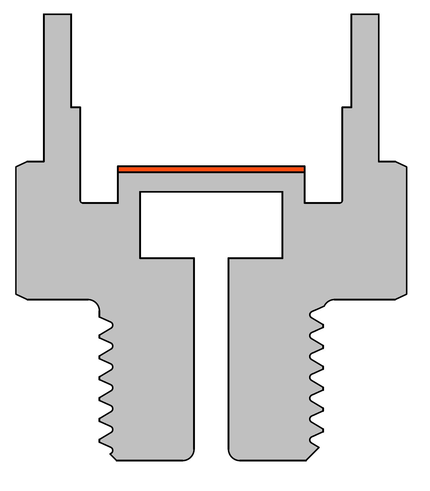
Silicon diaphragm in contact with media
A silicon diaphragm is the preferred form of piezoresistive pressure sensing element. This carries diffused-in strain gauges (DMS) whose electrical resistances change linearly with the sensed strain. The arrangement of the resistors are electrically designed as Wheatstone's measuring bridge, which has the property of changing its electrical voltage when the resistance changes.
In the wetted version, the medium to be measured is directly in contact with the silicon diaphragm. The sophisticated design of the sensor element with the measurement electronics mounted on the back of the diaphragm provides MP-Sensor pressure sensors with significantly increased media compatibility and media resistance.
Filtered, dry or lubricated compressed air as well as neutral gases are suitable media. In addition, the diaphragm is also suitable in principle for neutral liquids. The typical pressure range here is between -1 and 12 bar. Vacuum and pressure can also be implemented combined in one sensor. The main features of this silicon-based technology are the low-cost design, as well as high accuracy and long-term stability. In addition, this design is also particularly suitable for the smallest sensor designs.
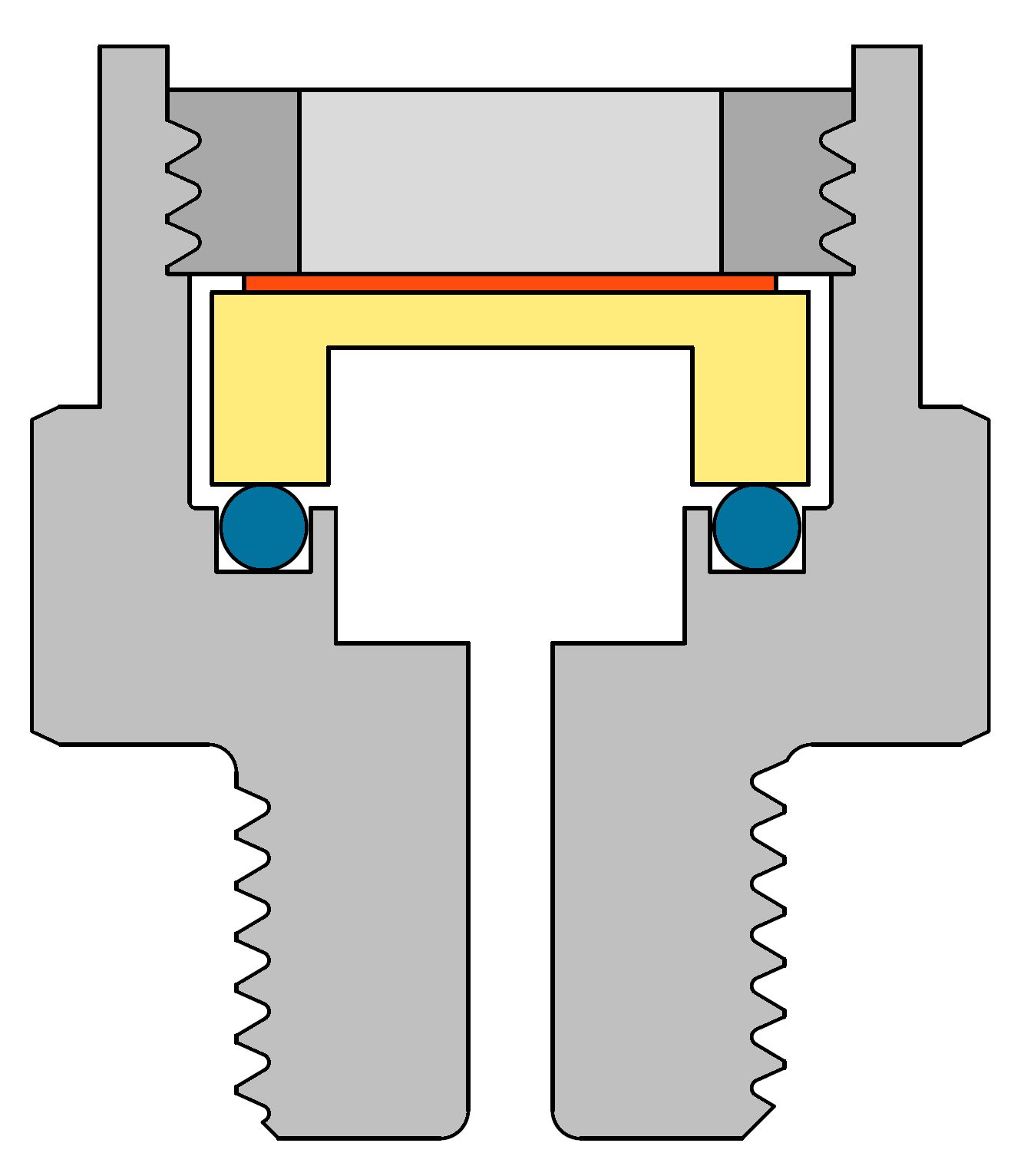
Silicon diaphragm media separated
In principle, the media-separated version has the same structure of the silicon diaphragm as the other version. However, the fluid to be measured is not directly applied to the silicon, but to a thin, elastic stainless steel diaphragm, which transmits the pressure to the diaphragm via an enclosed liquid for pressure transmission. Thus, the inherently sensitive silicon is protected and can be used independently of the fluid to be measured.
The main advantage, however, is that the flush stainless steel diaphragm has no dead space towards the fluid, so that the fluid can be measured hygienically, which is essential especially in the food industry. Due to the silicon diaphragm, there is also the advantage of high accuracy and long-term stability. Liquid and pasty media are particularly suitable as fluids to be measured for this technology. Caution is advised with solids or fluids containing solids, as the thin stainless steel diaphragm can easily be damaged and the pressure transmission medium then escapes. A pressure range of approx. -1 bar to 100 bar is usually available.
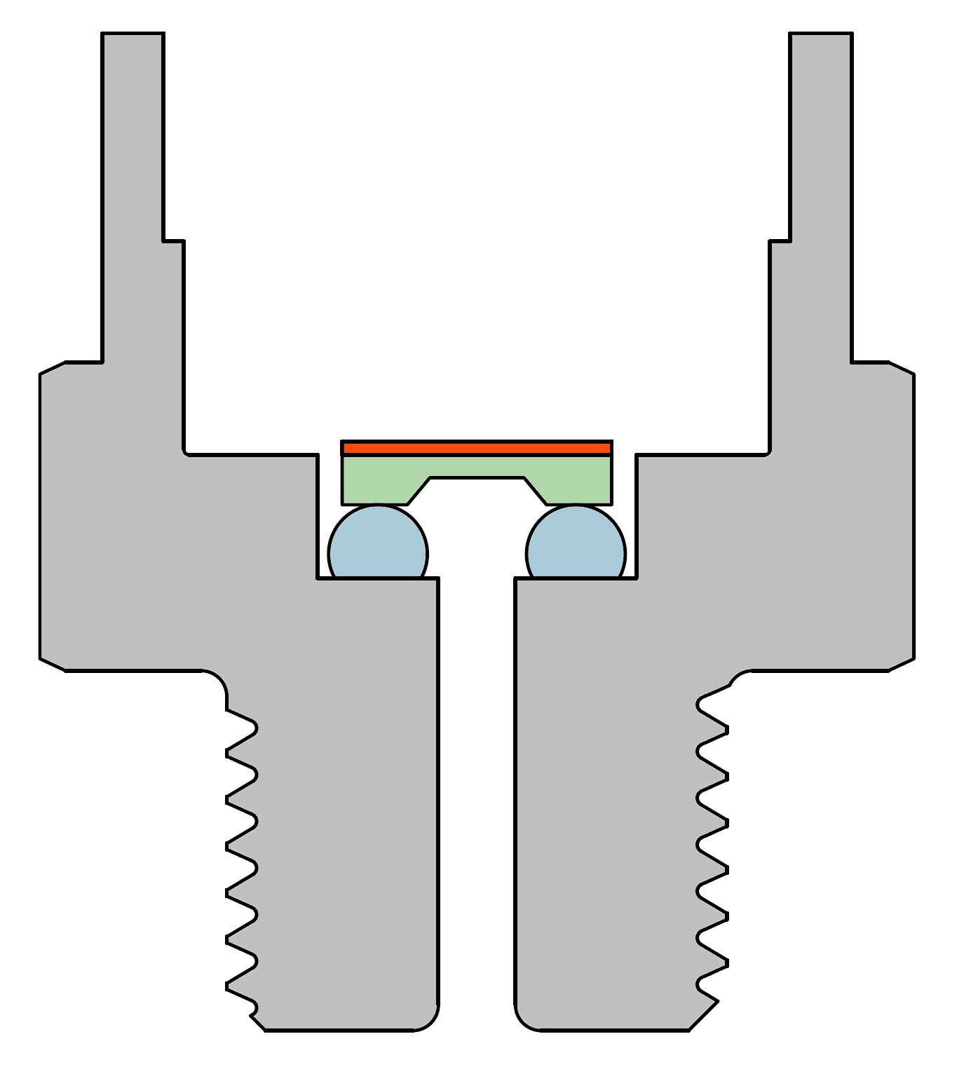
Ceramic diaphragm (thick film)
The basic body of this measuring cell typically consists of a ceramic monolith. A monolith is understood to be a single, non-joined ceramic body. The resistors are printed on the back of the membrane (=thin spot) using the thick-film process, and are thus also connected to form a Wheatstone measuring bridge, whose electrical behavior is then evaluated by the downstream electronics. The ambient air pressure acts on the back of the diaphragm, which is why only the relative pressure can be measured with a monolith. If the absolute pressure is to be measured, a hybrid ceramic diaphragm must be used, which consists of two ceramic pieces joined together and has a vacuum reference enclosed in it, for example.
Similar to silicon diaphragms, ceramic diaphragms are characterized by high accuracy and very good long-term stability. In addition, they are also very corrosion resistant. Since, on the one hand, the ceramic material requires a relatively thin wall to create a functional diaphragm and, on the other hand, the ceramic measuring cell is screwed to the sensor housing via a seal, the overload resistance is less than that of a welded stainless steel diaphragm due to the design.
Almost all material-compatible fluids or gases can be used as media. It should be noted that the fluid must also be compatible with the installed seal. The available pressure range is between -1 and 600 bar. When using a hybrid ceramic diaphragm, very small pressure ranges (mbar applications) can also be measured. Due to their flush design without dead space, they are also very well suited for hygienic applications and pasty media, even media containing solids are usually no problem compared to a flush stainless steel diaphragm.
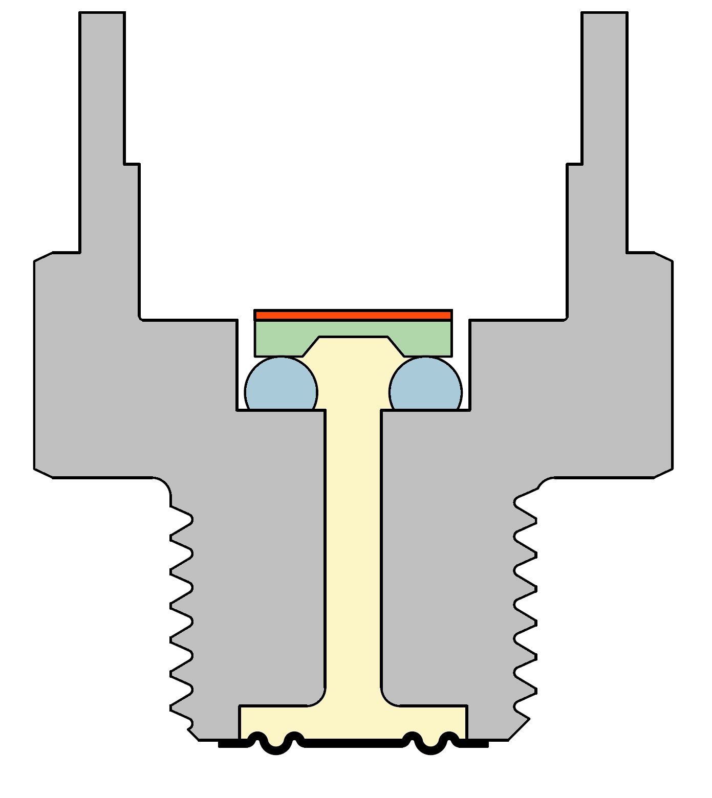
Stainless steel diaphragm (thin film)
The basic body of this measuring cell is made of stainless steel. The resistance structure with Wheatstone's measuring bridge is created by so-called photolithography in a high-vacuum chamber. Due to the fact that the diaphragm consists of a continuous stainless steel body, which is fully welded to the sensor housing, this type of pressure sensor is extremely resistant to overpressures and pressure peaks. The same applies to high shocks or vibrations.
On the other hand, the stainless steel diaphragm is only available with a reasonable accuracy above a certain pressure range (typically 25 bar and above), and also has a somewhat reduced long-term resistance compared to other diaphragm materials, since steel can have a minimal plastic component in addition to the elastic component when deformed, especially at overpressure. Almost all material-compatible fluids or gases can be used as the medium to be measured with this technology. Pressure ranges up to 2000 bar or higher are possible thanks to the fully welded diaphragm and the seals that are not required as a result.
Measuring cells at MP-SENSOR
MP-SENSOR currently uses mainly silicon diaphragms and ceramic diaphragms (monoliths) in the individual pressure sensors. The diaphragm used and the associated properties of the sensor significantly determine the industry in which the individual designs of pressure sensors are used. In pneumatic and vacuum technology applications, for example, it is mainly silicon-based measuring cells that are used, which is why the Pico, Nano or F08 designs are often installed in these areas. Whereas in general process technology, plant engineering or also in certain pneumatic applications with increased requirements, the designs with a ceramic measuring cell are used.
Accuracy (differentiation of terms)
Basic information:
Definition %FS: %FS means "% of Full Scale" and means that the percentage refers to the complete range of the measuring range. For a 0-10bar sensor, a value of 0.5%FS would mean that the maximum inaccuracy of the displayed measured value is 0.05 bar, regardless of the current pressure level.
Definition %FSO: %FSO means % of Full Scale Output and is to be understood in the same way as %FS, except that the percentage is not related to the displayed measured value, but to the output digital or analog signal.
Definition GP: The non-linearity is determined with the GP method (= limit point setting) by passing the reference line through the start of the characteristic curve and the end of the characteristic curve. With the same performance, the value according to GP is greater in terms of magnitude than with BFSL.
Definition BFSL: In the case of nonlinearity according to the BFSL method (=Best Fit Straight Line), the reference line is placed in such a way that the maximum downward and upward deviation are identical in magnitude, i.e. that it is averaged. This value can be up to factor 2 smaller than the value after limit point adjustment.
Specification "typ." / "typical": The addition "typ." or "typical" is often found in accuracy specifications. Caution is required here, because the addition means that not all delivered sensors achieve the specified value. Usually one can assume, if one takes the Gaussian normal distribution as a basis, that only approx. 65-70% of the delivered sensors comply with the declared value.
Information on the overall accuracy:
Overall accuracy: The maximum measurement deviation of the sensor to the actual value at room temperature (usually 23°C). The overall accuracy includes all relevant errors such as non-linearity, hysteresis error, non-repeatability, zero point error and span error.
Non-linearity: Non-linearity describes the deviation of the characteristic curve of a pressure sensor from the ideal characteristic curve, the reference line. There are two different methods for determining the deviation, the limit point (GP) method and the BFSL (Best Fit Straight Line) method.
Hysteresis error: Hysteresis error is defined as the maximum deviation that results for an exactly identical measuring point when this point is approached once from the bottom upwards and once from the top downwards.
Non-repeatability: The non-repeatability is the maximum deviation that results for an exactly identical measuring point when this point is repeatedly approached from the same direction.
Zero point error: The deviation of the measured value at ambient pressure is called zero point error. Temperature changes or sudden atmospheric fluctuations can lead to a zero point error. Furthermore, the long-term drift of the sensor affects the zero point and also leads to a zero point error.
Span Error: Span error is the deviation that prevails at the maximum rated pressure of the sensor. At the factory, both the zero point and the span are calibrated so that these two errors are almost zero at delivery.
Additional errors to the overall accuracy:
Long-term drift: The long-term drift is specified in addition to the individual errors of the overall accuracy, and describes the maximum possible drift that the sensor experiences over the years. This drift is specified in %/a, i.e. "percent per year".
Temperature error: All accuracy specifications always refer to room temperature. If the working temperature is higher or lower, the temperature error must also be taken into account. This is often specified per 10K temperature deviation from the room temperature, then the temperature error is also called temperature coefficient.
Often the different errors are also individually assigned a temperature coefficient, then the individual coefficients must be added to obtain an overall accuracy at a specific working temperature. The temperature has a very large influence on the measurement accuracy, which is why it is not uncommon for this to deteriorate by a factor of 3-4 at minimum or maximum operating temperature./span>